Table of Contents
The JEP 09150 - TWEEN (Towards a Wide Electrical Engineering Network) is the second TEMPUS project in the Faculty of Electrical Engineering from the Stefan cel Mare University of Suceava. The 1997/1998 academic year is the last year of this project.
The student mobility of the project during the three years of the project was:
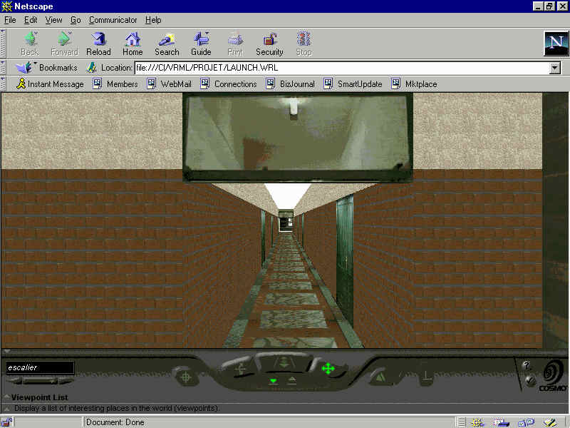
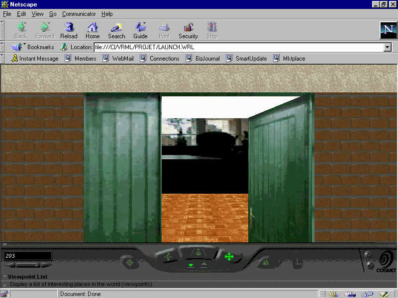
Resume. Le but du projet est la creation en 3 dimensions dun
espace virtuel representant une partie de luniversite Stefan Cel Mare
de Suceava. Lobjectif a atteindre est la visualisation dune piece du
batiment de lingenierie electrique. Pour le rendu realiste de cette modelisation,
nous utiliserons des textures plaquees (style le jeu Doom ) pour les
murs, le sol, le plafond
celles-ci seront fournies par lintermediaire
de prises de vue effectuees par une camera et traitees a laide dune video
blaster.
Introduction
Loutil de developpement utilise sera le langage VRML (Virtual Reality
Modeling Language) dans sa version 2.0, ce qui permettra eventuellement
par la suite une mise en place du produit sur le WEB.
I-Developpement du produit
Il faut associer un navigateur internet tel que Netscape ainsi que differents composants permettant la visualisation du code VRML. Le developpement sest effectue sous Netscape Communicator 4.01, le Plug-In associe etant SGI CosmoPlayer 2.0 disponible sur le site http://vrml.sgi.com. CosmoPlayer permet de naviguer plus aisement dans lunivers 3D que nous aurons construit et constitue avec ses differentes options une interface utilisateur tres interessante.
Nous avons choisi la version 2.0 de VRML afin de permettre des animations
ainsi quun rendu realiste (Remarque : la version 1.0 autorise la
traversee dobjet).
Sous VRML, la definition dun plan se fait comme suit:
Shape {
appearance Appearance {
#apparance de lobjet quon va definir ie.
Texture associee et #redimensionnement eventuel de limage
}
geometry IndexedFaceSet {
coord Coordinate {
point [definition des points constituant le plan ou la forme]
coordIndex[definition des differentes faces]
. . . etc.
}
}
}
DEF time TimeSensor {
definition des differents parametres du Timer
}
DEF orientation OrientationInterpolator {
key [definition des differents instants clefs lies aux positions clefs en pourcentage]
keyValue [positions clefs]
#il existe dautres types dinterpolateur
Transform {
type et parametres de la transformation (rotation, translation )
children [
Shape {
Definition de lobjet sur lequel on doit cliquer pour lancer lanimation
}
DEF touch TouchSensor { }
]
}
#Routage des differents elements
ROUTE TO
ROUTE TO
II-Utilisation du produit
Viewpoint {
jump TRUE
orientation 0 0 1 0
position 0 0 10
description "texte"
}jump est par defaut a TRUE et permet de passer dun point de vue a lautre rapidement. Si on le met a FALSE la transition est alors plus lente, on se deplace progressivement mais comme on avance en ligne droite, on traverse les murs par exemple ce qui nest pas interessant pour notre application.
III- Quelques resultats
Conclusions
Nous avons donc simule un petit univers 3D, dans lequel il est possible
de se deplacer. Il serait interessant de continuer le developpement du
batiment complet afin de linserer au sein dun monde virtuel representant
luniversite.
Enfin, on pourrait lintegrer dans une page WEB et faire des liens
vers dautres sites et pages.
References
Resume. Nous disposions de photos de divers alliages metalliques prises au microscope, et par un traitement informatique, nous devions pouvoir determiner le taux de carbone contenu dans les alliages. Ceci permet didentifier le type dalliage a partir de la concentration de carbone quil contient. Nous avions a realiser un logiciel capable deffectuer ce traitement sous environnement graphique WINDOWS 3.1.
Cahier des charges
Le cahier des charges est le suivant :
Nous disposions de Visual Basic 3, de Borland Pascal 7 et de Borland
C++ 3.1 pour developper ce projet.
La partie interface graphique etant tres importante dans le cahier
des charges, nous avons utilise Visual Basic 3 pour sa facilite de creation
de telles interfaces. Cependant, VB3, malgre son aspect visuel important,
demeure un langage interprete, et est donc plutot lent. Nous avons donc
rencontre des problemes de vitesses lors des divers traitements dimages,
que ce soit pour appliquer des filtres ou pour appliquer des calculs repetitifs.
Pour resoudre ces problemes, nous nous sommes oriente vers la creation
de DLL (Dynamic Link Library). Ce sont des modules autonomes utilisant
du code compile. Ils permetent donc deffectuer plus rapidement des traitements.
Nous avons ainsi decide dutiliser des fonctions ecrites en Pascal, et
compilees en DLL. Le choix decrire ces fonctions en Pascal plutot quen
C++ decoule du fait quapparement seul Borland Pascal 7 nous permetait
une creation aisee de ces modules.
Fonctionnement general du projet
Le projet est decompose en plusieurs formulaires qui interagissent entre-eux.
Le formulaire principal, qui est charge en premier, soccupe de la
gestion des autres formulaires. Avant tout traitement, il charge le formulaire
FileSelector qui permet de choisir les fichiers images a traiter (tout
en proposant un apercu de ces images).
Une fois les images choisies, le formulaire associe a limage originale
est affiche. Il est alors possible de choisir la zone dinteret sur limage
originale a laide de la souris. La zone selectionnee est alors affichee
dans un autre formulaire ou il est possible de choisir le traitement a
effectuer : Choisir les seuils a laide du formulaire histogramme pour
loperation de binarisation de limage, choisir differents filtres pour
ameliorer la qualite de limage originale. Le resultat final est affiche
dans le formulaire de la zone selectionnee.
Les images Bitmaps
La manipulation des images Bitmap a ete facilite sous Visual Basic. Lutilisation des objet Picture Box et Image permet dinserer directement des images au format Bitmap par des commandes simples. Le programmeur na pas a se soucier de lire dans le fichier pour aller chercher les informations utiles. Nous avons donc choisi de travailler avec ces objet pour manipuler les images a traiter.
Nous avons utilise une representation intermediaire des images. Nous
avons defini un tableau a deux dimensions. Ce choix est motive par le fait
que lacces a un tableau est plus rapide que lacces a la couleur dun
pixel dans un formulaire.
Le dialogue inter-forrmulaires
Le dialogue inter-formulaire se fait principalement a laide de variables globales definies dans un module general.
Nous utilisons aussi le fait que les objets dun formulaire sont accessible
a un autre. Par exemple cette propriete est utilisee lors de laffichage
de la zone de selection dans le formulaire final : les calculs sont effectues
dans un autre formulaire et les pixels sont modifies a partir de ce formulaire
exterieur.
Problemes rencontres et ameliorations possibles
Le probleme principal que nous avons recontre a ete limpossibilite de transmettre un tableau de Visual Basic a la DLL ecrite en Borland Pascal. Il semblerait quil y ait une incompatibilite entre le type array of integer de Pascal et le type array de Visual. Ce point nous a longtemps bloque lors de la realisation du projet. Nous avons donc du faire lensemble des traitements par Visual Basic, ce qui penalise fortement lapplication.
Une fois ce probleme resolu (peut-etre en programmant la DLL en Visual C++ comme cest apparement le cas de tous les programmeur sous Windows), lapplication prendrait beaucoup plus dampleur. Il serait alors possible dinclure des algorithmes de reconnaissance de formes. Nous avions a notre disposition de tels algorithmes, sans avoir pu les utiliser.
Il faut donc considerer cette application comme la base dun projet
beaucoup plus ambitieux.
En effet les fonctions permetant de recuperer la couleur dun pixel renvoient la couleur de ce pixel basee sur la couleur reelement affichee. Sur une machine ayant un affichage seulement en 8 couleurs, lhistogramme associe aux images traitees sera calcule sur seulement 8 couleurs et non sur 256. Les calculs sont donc moins fiables car la repartitions des couleurs sen trouve completement faussee.
Pour resoudre ce probleme, il faudrait travailler sur une copie de limage en memoire ou les couleurs utilisees seraient directement prises dans le fichier Bitmap (et donc independantes de laffichage utilise).
A noter que les images Bitmap prennent beaucoup de place en memoire. Lapplication necessite donc une machine ayant suffisament de memoire pour laccepter. Au cours de nos essais, il est apparu que 4 Mo ne suffisaient pas.
Voici quelques capture decran :
Bibliographie
I. Introduction
The theme of this project is VOICE RECOGNITION, in fact Voice Identification, wich is developped under LabVIEW program.
LabVIEW is a program development application, much like C or BASIC, or National Instruments LabWindows. Other programming system use text-based languages to create lines of code, while LabVIEW uses a graphical programming language to create programs in block diagram form.
LabVIEW, like C or BASIC, is a general-purpose pogramming system with
estensive libraries of function for any programming task. It includes libraries
for data acquisition, GPIB and serial instrument control, data analysis,
data presentation, and data storage. Also include conventional program
development tools, so you can set breakpoints, animate the execution to
see how data passes through the program, and single-step through the program
to make debugging and program development easier.
Application structure:
The voice recognition application is composed from 2 main parts:
This section is composed by a program written in "C" language under
DOS, and a hardware structure (the PCL-812 board that converts the analog
signal received from a amplifier).
The "C" program:
Is made to use the interrupts signals that comes from the PCL-812 board. The interrupt service routine get the 12-bit A/D conversion result from the coresponding I/O ports (BASE + 4 and BASE + 5) and put it into a buffer. The lenght of buffer is 4000 bytes. When this buffer is full, the interrupt is desactivated and this buffer is stored into a file. In this way, when the subject that is tested or is going to be appended into the database speech, this program get a set of 10 files, that containes about 5 seconds of speech.
Using the interrupt service routine, the maximum sampling frequency
is 25KHz, frequency that is big enough to sample the speech signal.
The analog interface description:
It is made with 2 operational amplifiers, type LM 741. In this configuration,
the amplification gain is about 80.
Board description:
The PCL-812 is a multi-function data aquisition card for IBM PC/XT/AT
computers, that have the following features:
single-ended analog input channels.
External trigger pulse.
Trigger Mode:
The PCL-812 A/D conversions can be triggered in any of three ways:
- software trigger
- on board programmable pacer
- external pulse trigger
There are three possible ways to perform the PCL-812 A/D data transfer:
- by program control
- interrupt routine
- DMA.
2 - Data processing section
Also, this part is composed by 2 sections:
- learning section
- comparing section ( voice identify )
A. Learning section
Use the files generates by the "data aquisition" section. First, this signal is filtered by a low pass filter, that limit the band frequency up to 3000 Hz. That section compute the FFT spectrum and the energy spectrum for every speech file, that are stored in two separated files: the file that contain the FFT transform for sampled signal and respectively the file that contain the energy spectrum for the sampled signal.
The FFT spectrum buffer and the energy spectrum buffer are the input parameters for two separated CINs.
A CIN is a block diagram node associated with a section of source code that is written in a conventional programming language ( for example, in "C" language ). The user compile the source code first and link it to form the executable code ( a .lsb file ). LabVIEW calls the executable code when the node executes, passing input data from the block diagram to the executable code, and returning data from the executable to the block diagram.
The meaning of these CINs is to store effectively the input buffers into these two files. Before this set of spectrums, in each file is a record that indicate that the following 12000 bytes ( corresponding for 10 samples ) belongs to a "anumit" subject.
One of this CINs also create a separated file that contain the list
of all subjects, and a number associated with each one, number that is
used to identify the corresponding section into the energy spectrum file
and the FFT spectrum file.
B. Comparing (testing) section
It is composed also from a low pass filter that limit the band frequency up to 3000 Hz, and these two elements that computes the FFT spectrum and the energy spectrum. Use also this type of files generated by the aquisition section, as input, but this time to compare the corresponding spectrums of these files with those allready existing.
The FFT and energy computed spetrums coresponding to a input file are used as input parameters for another two CINs.
These CINs are used to compare the FFT and energy spectrums that are the input parameters with the computed "weight centers" from the FFT spectrum database and respectively energy spectrum database with subjects. From FFT database and energy database are computed N "weight centers", N represent the number of subjects that are allready in. Then the FFT spectrum that is to be identifyed is compared with each "weight center" and are computed the "distances" between these two elements. The same steps are followed for the energy spectrum.
At the end of these precedures, will result two minimum distances, that, in a proportion of 70 % represents the differences between the spectrums of the subject that is to be tested and he's corresponding identification data that are allready into files.
The entire application, composed by these two structures does not work in real-time. This means that to make the aquisition, the PC has to be into DOS mode. Only in this mode the aquisition program work properly. After the aquisition is finished, the computer must be restarted into WINDOWS mode. Only in this way, with PCL812 is posible to get a sampling frequency about 25kHz.
At the end of this document are listed all CINs source files.
Abstract. The scope of this project was the implementation of digital filters with a 21xx DSP, and a software program to design filters and to download them on the DSP, using a serial port. Also, we have designed an algorithm for vocal recognition based on CROSSING ZERO techniques. The software tools were built in MATLAB and the communication between the DSP and the filter designer is established using a dynamic link library DLL constructed in BORLAND C for WINDOWS.
Introduction
We have designed a board with ADSP 2101, we have implemented the designed structure using the wrapping techniques and then we have designed the communication algorithms between the signal processor and the PC.
Once the communication was established, we have implemented a several algorithms using assembly code of ADSP 2101, algorithms such as :
· FIR filters for digital signal processing
· IIR filters using direct form second-order section
In order to achieve the scope mentioned above we have to propose and to implement a solution for the following requirements:
· the software must have a user friendly interface
· the whole process must be interactive
· the routines must be designed for ADSP 2181 and 2101
· the filter process and voice recognition process must be real
time processing
· the user must have control of all coefficients and all parameters
involved in the process
· also the process must be easy for late updating
Designing this software we have used the following resources:
· MATLAB 4.5 built-in functions
· SIMULINK TOOLBOX PROCESSING
· SIGNAL PROCESSING TOOLBOX
· BORLAND C++ 4.5
· ADSP 2181 EZ-kit LITE
· Assembler code for ADSP 21xx family
· IBM PC compatible system (486 100Mhz, 16Mb RAM or higher)
· 8 Mb of hard disk space
The system consist in one ADSP 2101 digital signal processor provided by Analogue Devices, which is connected to the IBM-PC control system using the serial interface RS-232 industrial standard. The analogue signals are converted to digital words using serial CODEC interface, AD 1847. The main software routines are stored in EPROM memory, 27C256, and the processed data is stored in a RAM memory, 65256.
The system was designed to be used as a Data Acquisition System for the voice signals. The DSP processor takes the incoming signal from the CODEC in a digital format (16bits-linear PCM) and this procedure is a serial data transmission hosted by the processor using the communication software designed on this purpose. The incoming data is stored in the RAM memory and the processor applies on this data the filter algorithms stored in its internal RAM. All the initialisation procedures needed for a safe and quick digital data processing are stored in the ROM memory. The filter type and its related coefficients are controlled and wrote in the Program Memory using the serial RS-232 connection hosted by a MAX 232 interface driver circuit.
The system has three main interface-devices, which are described below:
· An analogue to digital interface which converts the analogue incoming signals (voice signals) in PCM digital signals using a Programmable Gain and Attenuation and sample rates from 5.5 KHz to 48 KHz . The interface is based on a 16-bit serial-port stereo CODEC (AD 1847) which is a Delta-Sigma A/D D/A converter.
· A serial interface between the digital signal processor ADSP 2101 and the IBM-PC compatible system. This is also a serial interface based on the industrial standard RS 232 implemented with MAX 232 circuit.
· A user interface which consist in a software program (MATLAB)
which enables the user to control the filter type and its coefficients,
in order to accomplish the appropriate task.
The built-in functions, which we have used for filter design, are:
· Butter generates Butterworth filter
· Bessel generates Bessel filter
· Cheby1 and Cheby2 generates Tchebyshev filter
· Ellip generates Elliptic filter
· Fir1 generates finite impulse response filter, type one
A filter is essentially a system or network, that selectively changes
the waveshape, amplitude-frequency and/or phase-frequency characteristics
of a signal in a desired manner. Common filtering objectives are to improve
the quality of a signal (for example, to remove or reduce noise), to extract
information from signals or to separate two or more signals previously
combined to make, for example, efficient use of an available communication
channel.
Digital filters are broadly divided into two classes, namely infinite
impulse response (IIR) and finite impulse response (FIR) filters.
The basic FIR filters is characterised by the following two equations:
![]()
![]()
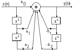
The transversal (or tapped delay) structure is depicted in the following picture:
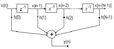
In the figure, the symbol z-1 represents a delay of one sample or unit
of time. Thus x(n-1) is x(n) delayed by one sample. In digital implementations,
the boxes labelled z-1 could represent shift registers or more commonly
memory locations in a RAM. The transversal filter structure is the most
popular FIR structure.
The output sample, y(n), is a weighted sum of the present input, x(n), and N-1 previous samples of the input, that is x(n-1) to x(n-N). For the transversal structure, the computation of each output sample, y(n), requires:
- N-1 memory locations to store the N-1 input samples
- N memory locations to store the N coefficients
- N multiplications
- N-1 additions
The IIR filter is characterised by the following equation:
![]()
In practice, H(z) is normally broken down into smaller sections, typically second order blocks, which are then connected up in cascade.
Examples of practical second-order building block used in realising
higher order IIR filters are depicted in the figure:
The second filter section is a direct realisation of the second-order
IIR equation. It is characterised by the following equations:
![]()
![]()
The filter block given in previous figure is in general a second-order section. Several other filter blocks can be derived from them.
For voice recognition algorithm we have used the technique called crossing zeros. First we are using the sampling frequency of 5512Hz and we filter the input sound with two FIR filters. One is a lowpass filter with the cut-off frequency at 800Hz and the degree of 100 and a bandpass filter with the cut-off frequencies at 800Hz and 2000Hz and the degree of 100. After this we must check if a word was said and we do this by comparing the energy of sound with a constant and when its bigger than this, the word will be recorded. Then in time of one second we are counting the crossing zeros using sixty frames. When this is finished, the counts of crossings will be send to the PC, using serial communication. From this point on there can be taken a lot of different approaches. But first you have to implement two different steps: the learning procedure and the listening one. The basic idea is that first, the program must learn a word by taking three or more samples and make with these an average of the word. We also have considered a small tolerance because the words although for us they are the same, for the computer there are big differences between the same spoken words. For recognising a word, we search in the database with the learned words and make the difference between. Then we use the closest match and if it is within the tolerance value, then we say that we have found the spoken word, if not, then the word is not recognised. But the algorithm is still in the stage of development.
The main conclusions regarding digital filtering are:
· The FIR/IIR filters are effective and easy to use.
· MATLAB is a proper tool for designing these kinds of applications
and the math functions included are very easy to use.
· The digital filters implemented here can be used in a wide
area of applications such as: echo cancellation, noise reduction in industrial
systems, audio applications in communications and multimedia technology.
The main conclusions regarding the voice recognition are:
· The DSP and MATLAB are working properly together and show good
results using the filters designed by us.
· The algorithm could be also improved to get more accurate
results.
· The low cost and the viability of the method proposed recommends
this design to be implemented in a large scale taking into account the
very large interest for such algorithms in applications such as: person
recognition, words recognition, intelligent controls, interactive systems
using vocal commands and more.
Description
The XY- laserwriter is a construction where two mirrors are being moved by two stepper motors. Those are driven by the computer program that we have wrote. Herewith we become a bending in the horizontal and the vertical direction. To get a stable image, it is necessary to overwrite this projection several times a second.
The mechanical part is presented in the figure 1. It can be seen the
laser pointer (11) and the mirror (the OY mirror has number 5)
The software must provide us to simulate the image first on the screen.
The images are created on a matrix with the numeric keyboard or by a text
editor. There are electronics needed that drive the stepper motors on a
sufficient save and fast way. And by the mechanical design we have to keep
in mind that we need fast and sudden movements with as little inertion
as possible.
The structure
To keep the main program simple to understand and easy to read again, one must try to keep it as short as possible. That's why our main program just exists of calling up to two subprograms. Those are the ones who do the job.
Each of the subprograms contains two include files. But one of the files
is common for both of the subprograms. It is about file-handling.
The first subprogram is able to make and save graphical images.
The second accounts for the calibration of the laser beam and sending the information. It is also based on the file " .h " and on the include file for ports. By the port file we use exor byte manipulator to invert the bytes (select,...).
Table with data to drive one engine
| D3 | D2 | D1 | D0 C1 | C2 I1 | I0
| 0 0 1 1 1 X +1 0 1
| 0 0 1 0 1 0 +1 +1/3 2
| 0 0 0 1 1 0 +1 +2/3 3
| 0 0 0 0 1 0 +1 +1 4
| 0 1 0 0 1 0 +2/3 +1 5
| 1 0 0 0 1 0 +1/3 +1 6
| 1 1 0 0 X 0 0 +1 7
| 1 0 0 0 0 0 -1/3 +1 8
| 0 1 0 0 0 0 -2/3 +1 9
| 0 0 0 0 0 0 -1 +1 10
| 0 0 0 1 0 0 -1 +2/3 11
| 0 0 1 0 0 0 -1 +1/3 12
| 0 0 1 1 0 x -1 0 13
| 0 0 1 0 0 1 -1 -1/3 14
| 0 0 0 1 0 1 -1 -2/3 15
| 0 0 0 0 0 1 -1 -1 16
| 0 1 0 0 0 1 -2/3 -1 17
| 1 0 0 0 0 1 -1/3 -1 18
| 1 1 0 0 x 1 0 -1 19
| 1 0 0 0 1 1 +1/3 -1 20
| 0 1 0 0 1 1 +2/3 -1 21
| 0 0 0 0 1 1 +1 -1 22
| 0 0 0 1 1 1 +1 -2/3 23
| 0 0 1 0 1 1 +1 -1/3 24
| 0 0 1 1 1 X +1 0 1
In this table you see 4 bits (D3, D2, D1, D0) that determine the size of the current and 2 bits (C1, C0) that determine the direction of the current. The program will place the data on the right lines depending on which engine has to turn and in what direction.
This table is based on data sheet of the L6219. When the program runs
for the first time both engines are initialised on the first row. Depending
on the data input the computer will shift up and down in the table. When
he comes at last row and he has to turn further he automatically jumps
to the first. In the opposite way it is just the same.
More torque at a higher number of revolutions
Higher torque at faster speeds are possible if a current generator is used. In this application the supply voltage is chosen as high possible to increase the currents rate of change. The current generator itself limits only the phase current and becomes active only the moment in which the coil current has reached its set nominal value. Up to this value the current generator is in saturation and the supply voltage is applied directly to the winding.
Consequently at higher step rates the desired current can be maintained in the winding for a longer time. The torque decrease starts only at much higher speeds.
It is obvious that the power increases in the upper torque range where it is normally needed, as the load to be driven draws most energy from the motor in this range.
We should develop a system that allows remote reading of electric power consumption counters.
The system consists of the following parts:
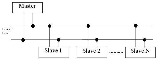
For this reason the Master and the Slaves should be equipped with power line modems.
A power line modem allows to transfer signals on power lines. This is the simplest and cheapest way to do the connection.
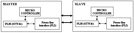
We used the ST7536, a single chip half-duplex synchronous FSK-modulator. For a complete communication system, a micro-controller and a Power Line Interface (PLI) are needed. Furthermore, because it isnt possible to make high value capacitors and resistors on the integrated circuit, it is necessary to add some external ones.
We used, for our work, the SGS-Thomson Application Note for the ST7536 and we followed the instructions on that document.
We were especially involved in the project of the analogue part of the system, that is the power line interface.
The powerline interface connects the ST7536 to the powerline. The PLI has been designed according to ENEL specifications.
In transmit mode the PLI amplifies and filters the signal Analogue Transmit Output from the ST7536. A buffer is used to protect the ST7536 and to drive the following stages of the powerline interface.
To suppress the harmonics, but the second, a low pass filter is used. The filtered signal is sent to a power amplifier, which has to drive powerlines with impedances from 1 to 100W by the transformer.
The transformer is not only used to put signals on the powerlines; it is also used as a band pass filter, in order to suppress the second harmonic of the transmit signal to a level of less than -72 dB.
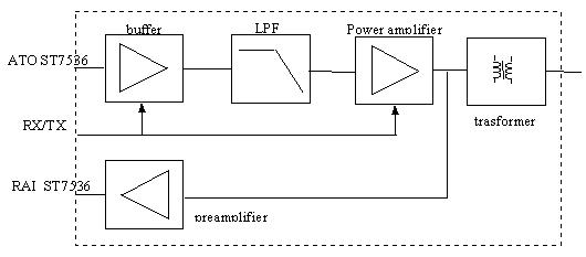
In receive mode the transformer extracts the signal from the powerline.
This signal is amplified in the preamplifier to a level of 34 dB.
The buffer and the power amplifier are switched off in receive mode,
in order to avoid low output impedance of the power amplifier which attenuates
the received signal. It is worth to stress the role of the power
amplifier.
It increases the output signal of the operational amplifier and the
low pass filter. The output stage is an AB Class; such stage merges the
best qualities of A and B Class amplifiers: the high linearity of the A
Class and the high efficiency of the B Class.
A transformer is used to connect the power amplifier and the preamplifier to the powerline. This transformer does a lot of functions:
In receiving mode, after being extracted by the transformer, the received signals are preamplified before being sent to the Receive Analogue Input of the St7536. It is necessary to use a preamplifier because we need a receive sensitivity of 1.5 mVRMS, according to the specifications.
In receive mode the power amplifier is virtually disconnected to avoid its low output impedance attenuating the received signals and in order to avoid power consumption.
After filtering, the signals are amplified with, an inverting amplifier with a gain set (with two resistors) at 40 dB.
Here is the complete circuit diagram (ST7536 & Power Line Interface):
The second step was the development of the board schematic using Protel Design System v. 3.1.1. ( The above schematic was made using that program). After that, we carried out the board layout using Protel Electronic Design System v. 2.8.0.
For a complete system it is necessary to use a microcontroller. The SGS-Thompson Application Note advises to use a ST6 microcontroller. By an accurate programming of the microcontroller it is possible to develop a n appropriate protocol. It is also possible to interface the system with a personal computer, thus simulating the controller and processing the data using special programs such as Labview and Matlab.
Unfortunately we did not have enough time to develop the control system, however we think that it could be used another microcontroller, instead of the ST6 with the same results.